Image of the day

Captured by
Douglas Rollain

M20 Trifid Nebula in LRGBHa

My Account

New to Astromart?

Register an account...

Need Help?

Cylindrical observatory construction

Started by jeyjey, 09/05/2005 06:35PM
Posted 09/05/2005 06:35PM Opening Post
Now that we're on to the timber framing, I've started a new thread.

Just to recap, the pier and pad design and construction were detailed in: http://www.astromart.com/forums/viewpost.asp?forum_post_id=355146.

Here's the result of that stage, and the foundation for the next:

Attached Image:

jeyjey's attachment for post 26572
Posted 09/05/2005 06:37PM #1
While a few dimensions have changed slightly, the original plan sketch still gives a reasonable idea of the goal:

Attached Image:

jeyjey's attachment for post 95631
Posted 09/05/2005 06:39PM #2
First there were rebar rings, now plywood....

Here's a picture of 34 plywood arcs rough-cut with a jigsaw. Standing against them is a hand-planed template which will be used with a trim-cutter in a router to finish-cut all the rest.

Then they all get glued and screwed together to form double-layer top and bottom plates for the observatory walls.


Attached Image:

jeyjey's attachment for post 95632
Posted 09/10/2005 09:08PM #3
Progress has stalled a bit. Last week I got to the point where some of my sketchy plans needed all the details worked out, but they weren't coming easy.

The first was how to fit a flat door into a cylinder. I had thought that the radius would be sufficient that it really wouldn't matter, but the center of a 32" door turns out to be some 4" in from the edge of the pad. Not much of a weathering detail (although I could put a rounded drip board on the bottom). Since my house was built by the same man (and architect) as Armagh Observatory, I went there for inspiration. And lo and behold, if there isn't a building added in the 1880's for the Grubb 10" refractor (lower right in picture) that looks remarkably similar to what I'm building. But it gets better: it also has a very nice detail of a rounded-roof vestibule for the door! shocked

I've pretty much worked out how to fit that into my plans (although in my case the vestibule will only be a few inches deep -- just enough to give profile to the curved roof and a flat surface on the cylinder for the door).

Next up was how to suspend a floor composed of parallel joists inside a cylindrical studded wall. This required building a bit of a platform in my old kitchen (the floor wasn't level enough to just use it), and then doing a bunch of test-fits to see what was going to work. After several days (!) of moving things around and scratching my head, I think I've also figured that part out.

So hopefully, things will start to progress again...
8)

Attached Image:

jeyjey's attachment for post 95849
Posted 09/12/2005 02:21PM #4
The outside of the building is composed of a 10' diameter timber studded wall. The current plan calls for plywood, tar paper, expanded metal, and sand & cement plaster (aka stucco, for those in the States).

Since the building is 10' tall, there will be horizontal joints in the plywood as well as vertical. I've found that 1/4" plywood is about the thickest that will bend easily around the radius. (3/8" will bend around it, but it seems fairly highly stressed when doing so.)

So... current plan is two layers of 1/4" with staggered joints.

-- Does this sound reasonable?

-- Or am I asking for more trouble (with condensation between the two layers of plywood)?

-- Lastly, glued together? ...or just layered and screwed (w/ exterior grade screws)?

Thanks,
-- Jeff.
Posted 09/14/2005 09:53PM #5
I built a platform out in the old kitchen (the floor's very uneven) so we could do some test assemblies. It proved very handy in laying out all the floor joists on top of one of the plywood rings as we went, measuring, cutting, mortising, tenoning, and quarter-housing.

Hobbies are great. Where else can you go this far over the top and still enjoy it? 8)

Attached Image:

jeyjey's attachment for post 96030
Posted 09/20/2005 07:12PM #6
The floor joists will be supported on noggings housed 1/4" into the vertical studs of the perimeter wall. Here are a bunch of studs after being notched with a router.

Attached Image:

jeyjey's attachment for post 96233
Posted 09/21/2005 01:53PM #7
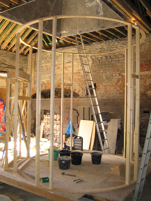
Here are a couple of shots of just enough studs in to hold up the top ring, so we can see how it all goes together.

Attached Image:

jeyjey's attachment for post 96264
Posted 09/23/2005 10:14PM #8
Here we've planed and thicknessed a couple of 2x7s for stringers, and routed out housings for the stair treads. The stair treads are planed and thicknessed 2x9s, with a curve molded on the front using a spindle molder.

This picture shows a tread getting ready to have its two front corners rounded down with a rasp.

Attached Image:

jeyjey's attachment for post 96384
Posted 09/24/2005 11:08PM #9
We screwed in a couple of layers of 1/4" plywood above the door so that we could scribe in the back (curved) line of the door vestibule roof. It's 2 layers of 3/8" plywood (glued and screwed) over a shaped header.

Attached Image:

jeyjey's attachment for post 96442